1) Purpose and context
This power subsystem is designed for a solar‑powered, battery‑backed IoT node used in agricultural monitoring and remote sensing. The node must keep a microcontroller (MCU) and essential logic alive 24/7 from a continuous 3.3 V rail, while switchable auxiliary rails (12 V, 5 V, 3.3 V_AUX) power sensors, radios, and actuators only when needed via a common EN_AUX signal. The design must tolerate a harsh outdoor environment (temperature swings, moisture, dirt, ESD), handle panel voltages up to the high‑20 V range typical of “12 V‑class” PV modules, and protect the Li‑ion battery pack from abuse (over/under‑voltage and current events) with detailed state‑of‑charge visibility.
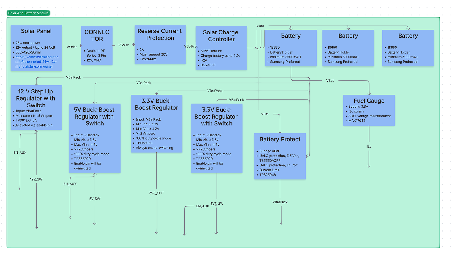
At a high level (see the provided block diagram), energy flows from a rugged Deutsch DT solar connector into reverse‑current protection and an MPPT solar charger, then into a 1‑cell 18650 battery pack (cells in parallel for capacity). Downstream of the pack, a protect eFuse enforces UVLO/OVLO and current limiting. One always‑on 3.3 V buck‑boost regulator feeds the MCU (“3V3_CNT”). Three auxiliary regulators (12 V step‑up, 5 V buck‑boost, 3.3 V buck‑boost) are gated by EN_AUX to minimize idle draw. A fuel‑gauge IC reports SoC and voltage to the MCU over I²C.
Design decisions are justified below with alternatives and trade‑offs. Each section ends with a concise comparison table. Inline numeric citations use APA‑style bracket numbering (e.g., [4]); the full references list appears at the end.
2) Solar input and front‑end
2.1 PV panel and field connector
What we used and why. The system expects a “12 V‑class” PV module (≈17–18 V at maximum power, ≈21–22 V open‑circuit, depending on temperature) connected through a Deutsch DT‑series 2‑pin sealed connector. DT connectors are widely used in agricultural and off‑highway equipment for their IP‑rated seals, latch robustness, and vibration resistance, reducing water ingress and intermittent contact risks that plague generic DC barrel jacks in the field [14]. The higher Voc of “12 V” panels is normal and ensures headroom for charging; this is handled by the downstream MPPT charger [20]. RS ComponentsAltE Store
Alternatives considered. M8 circular connectors (industrial sensors), and unsealed barrel jacks. DT won for sealing and tactile locking; M8s are excellent but require panel‑mount bulkheads and are costlier; barrel jacks were rejected for poor ingress protection.
| Option | IP/Sealing | Current rating | Field serviceability | Typical cost | Notes |
|---|---|---|---|---|---|
| Deutsch DT‑2 (chosen) | IP67/68 with seals | ~13 A per size‑16 contact | Crimp contacts, positive latch | $$ | Proven in ag/off‑road [14] |
| M8 A‑coded | IP67/68 | 3–4 A typical | Threaded; panel‑mount bulkhead | $$$ | Great, but higher BoM and assembly cost |
| DC barrel jack | Poor | 1–5 A | Easy | $ | Not weatherproof—unsuitable outdoors |
2.2 Reverse‑current and surge protection (PV side)
What we used and why. A high‑voltage eFuse with reverse‑polarity/ reverse‑current blocking (TI TPS2660x family) protects the system from wiring mistakes and prevents the battery from back‑feeding a dark panel. Compared with a Schottky diode, the eFuse avoids large conduction losses, supports adjustable current limit, and tolerates the ≈30 V worst‑case Voc/ transients from “12 V” panels [3]. Texas Instruments
Alternatives considered.
| Option | Conduction loss | Reverse blocking | Accuracy/features | Complexity | Suitability |
|---|---|---|---|---|---|
| eFuse TPS2660x (chosen) | Low (MOSFET) | Yes (OVP, RCP) | OVP/UVP/ILIM, telemetry (varies) | Medium | Best overall protection to 60 V [3] |
| Ideal‑diode controller (LTC4412, LM5050‑1) | Very low | Yes | No current limit; add parts for OVP | Medium | Efficient, but less comprehensive [8][9] |
| Schottky diode | High | Partially | None | Low | Simpler; unacceptable power loss at >1–2 A |
Rationale: In a remote node, survivability beats small BoM savings. The eFuse gives correct behavior under miswiring, hot‑plug, and panel brownouts.
2.3 MPPT solar charge controller
What we used and why. TI bq24650—a synchronous buck charger with integrated constant‑voltage MPPT loop. It reduces charge current so the panel operates near its programmed MPP and supports a wide PV input range, ideal for “12 V‑class” modules [4]. The device handles pre‑charge, termination, and status; it charges a 1‑cell Li‑ion pack to 4.2 V (adjustable via feedback). Texas InstrumentsFarnell
Alternatives considered.
| IC | Topology | Input range | MPPT method | Max I_CHG | Notes |
|---|---|---|---|---|---|
| bq24650 (chosen) | Buck, ext. FETs | 5–28 V (typ) | Constant‑voltage input regulation | 5 A‑class (design‑dependent) | Well‑documented PV tracking [4] |
| ADI LT3652 | Monolithic buck | 4.95–32 V | Input‑voltage regulation (peak power tracking) | Up to 2 A | Excellent for compact, moderate‑current designs [12] |
| CN3791 | Buck controller | 4.5–28 V | MPPT (1.205 V ref) | Up to 4 A | Cost‑effective; fewer protections [13] |
| MCP73871 | Linear | 3.5–6 V | None (power‑path mgr) | ~1 A | Good for USB/small PV; poor efficiency at high Vin [11] |
Rationale: The bq24650 offers the best balance of input range, efficiency, and documented MPPT behavior for our panel class. If the system prioritized minimal BoM over peak charge current, LT3652 would be a credible alternative. Analog Devices
Battery longevity note. If lifetime cycling is paramount, the charge voltage can be reduced (e.g., 4.10 V) to extend cycle life at the cost of capacity; industry literature consistently reports large cycle‑life gains when charging below 4.2 V [6]. We keep 4.20 V here to preserve full capacity for high‑peak loads, with the option to derate later via the feedback divider. Battery University
3) Energy storage: 1‑cell 18650 battery pack
What we used and why. A 1S (single‑cell) Li‑ion pack built from multiple 18650 cells in parallel to increase capacity and peak current while keeping the system at 3.0–4.2 V. This keeps downstream converters efficient and allows a single charger IC. Using reputable cells (e.g., Samsung 30Q/35E) ensures consistent impedance and cycle life, important for cold starts and radio bursts. Typical capacities are 3000–3500 mAh per cell (exact choice is a BoM decision). For long life in duty‑cycled applications, we avoid deep discharge (see UVLO in §3) and, if needed, can adopt a lower float voltage per note above [6].
Alternatives considered. 2S Li‑ion (higher bus simplifies 12 V boost but increases parts count), or LiFePO₄ 1S (safer/higher cycle life but lower energy density, different charger). We chose 1S Li‑ion to minimize IC diversity and maintain high converter efficiency at light loads.
4) Battery‑side protection (eFuse + supervisors)
What we used and why. A battery‑side eFuse (TI TPS25946) provides adjustable current limiting, UVLO and OVLO, inrush control, and reverse‑current control. This device cleanly disconnects the pack from downstream rails on faults (shorts, over‑voltage), limiting stress and preventing latch‑ups when loads hot‑plug. A dedicated voltage supervisor provides precise UVLO around 3.3 V (to preserve cell health) and OVLO around 4.1 V (optionally used if we choose to limit the system bus during charge handover). The eFuse’s integrated FET and control loop are significantly more predictable than polymer fuses + discrete MOSFETs in low‑power electronics [7]. Texas Instruments
Alternatives considered.
| Option | Pros | Cons | Suitability |
|---|---|---|---|
| eFuse TPS25946 (chosen) | ILIM/OVLO/UVLO, inrush control, reverse current features | Adds IC cost; layout care | Robust, tunable protection [7] |
| Pack‑level protector (DW01A + MOSFETs) | Very low cost, ubiquitous | Fixed thresholds, no current telemetry or ramp | OK for consumer packs; limited system control [18] |
| “Rely on charger limits only” | Minimal BoM | No downstream short protection; risky in field | Not acceptable |
5) System rails, enables, and power‑gating
A single always‑on 3.3 V rail powers the MCU and fuel gauge. Aux rails (12 V, 5 V, 3.3 V_AUX) are disabled by default and only enabled when tasks require them. This power‑gating strategy slashes idle draw by removing both regulator quiescent current and sensor leakage when not in use. Where loads have large input capacitance (e.g., radios, solenoids), the enable sequence lets the eFuse and regulator soft‑starts tame inrush. If particularly aggressive inrush control is required per load, a small load switch (e.g., TPS22965) at the rail point‑of‑load can add extra slew‑rate control with microamp IQ [17]. Texas Instruments
5.1 Always‑on 3.3 V (MCU rail): synchronous buck‑boost (TPS63020)
What we used and why. The TPS63020 maintains 3.3 V across the full battery span (≈3.0–4.2 V), seamlessly transitioning between buck and boost. Its 100% duty‑cycle mode minimizes switching losses and ripple when Vin is only slightly above Vout (common at 3.5–3.8 V), which is ideal for a quiet MCU rail. It offers solid light‑load efficiency without the dropout problems a buck‑only would have near 3.3 V [1]. Texas Instruments
Key alternatives (and when they might win).
| Option | Efficiency across 3.0–4.2 V | IQ (typ.) | EMI/noise | Notes |
|---|---|---|---|---|
| Buck‑boost TPS63020 (chosen) | High and flat (buck↔boost) | Low | Good; 100% duty in buck | Best regulation at all SoC [1] |
| LDO (e.g., TPS7A02) | Drops as Vin↑; worst at 4.2 V | Ultra‑low | Excellent | Great if load is ultra‑low and noise is critical; but loses >20% at 4.2→3.3 V [15] |
| Buck‑only (TPS62130) | High if Vin≫Vout | Low | Good | Fails as Vin approaches 3.3 V (dropout) [11] |
Why we chose buck‑boost: We need guaranteed 3.3 V at any SoC with good efficiency and low ripple for the MCU and I²C devices.
5.2 5 V auxiliary rail: synchronous buck‑boost (TPS63020)
This rail powers 5 V peripherals when EN_AUX is asserted. The topology and IC are intentionally the same as §4.1 to reduce BoM diversity and reuse layout know‑how. Here the converter operates exclusively in boost region (since 3.0–4.2 V → 5 V). A boost‑only converter (e.g., TPS61023) is a valid alternative and can be slightly cheaper with very low IQ, but reusing TPS63020 simplified qualification and thermal modeling [10]. No need to repeat the electromagnetic/compensation discussion already covered in §4.1. Texas Instruments
Targeted differences vs §4.1:
• Heavier burst loads expected (USB‑class sensors, analog front‑ends), so we size the inductor and output caps accordingly.
• Since the rail is off most of the time, its shutdown IQ dominates—TPS63020’s disable current is sufficiently low for our budget [1].
Focused comparison for 5 V:
| Option | Vout | Notes |
|---|---|---|
| TPS63020 (chosen) | 5 V | Reuse; strong transient handling [1] |
| TPS61023 | 5 V | Simpler boost‑only; excellent light‑load IQ [10] |
5.3 12 V auxiliary rail: synchronous boost (TPS61377)
What we used and why. The TPS61377 delivers 12 V (and higher) from the 1S bus with 6 A peak switch current capability and ~70 µA IQ; it is well‑suited to solenoids, valves, and instrumentation that need 12 V only intermittently. It supports selectable PFM/PWM for light‑load efficiency, and has OVP/OCP protections. In our design, its enable is tied to EN_AUX [2]. Texas InstrumentsMouser Electronics
Alternatives considered.
| Option | Topology | Pros | Cons | Suitability |
|---|---|---|---|---|
| TPS61377 (chosen) | Boost | High output power, low IQ, compact | Needs careful layout | Best balance for 12–24 V rails [2] |
| SEPIC controller (LT3757 / LM3478) | SEPIC/Boost | Very wide Vin–Vout, can step‑up/down | External FETs; larger BoM | Overkill here; shines with wide input [16] |
| Buck‑boost module | Integrated | Fast to implement | Cost/size | Valid for prototypes only |
6) Fuel gauging and telemetry
What we used and why. MAX17043 fuel gauge with the vendor’s ModelGauge algorithm. It reports state‑of‑charge and cell voltage over I²C without a sense resistor, minimizing losses and simplifying layout. Its quick‑start and alert thresholds make it easy to implement robust low‑battery behaviors on the MCU [5]. Analog Devices
Alternatives considered.
| IC | Sense resistor | Algorithm | Notes |
|---|---|---|---|
| MAX17043 (chosen) | No | Model‑based SoC | Simple integration, low overhead [5] |
| bq27441 | Yes | Impedance‑track CC | High accuracy over aging; more setup [3rd‑party literature, typical] |
| MAX17048 | No | ModelGauge m3 | Newer family; similar use case |
Why we chose MAX17043: We needed detailed monitoring with minimal BoM/firmware overhead and no shunt losses—ideal for an energy‑constrained node.
7) System integration notes
- EN_AUX power domaining. The MCU keeps 3V3_CNT always on. When tasks require peripherals, it asserts EN_AUX. The three auxiliary regulators share EN_AUX, but time‑staggered enables can be added in firmware if inrush events brown the bus. Load‑switches (TPS22965) can be added at individual loads that still need slew‑rate control [17]. Texas Instruments
- Grounding and layout. Keep PV return, charger power ground, and switching regulators on a low‑impedance ground plane. Star the eFuse/battery return into that plane to avoid sense errors in the charger/current‑limit network.
- Brown‑in/out behavior. The battery‑side eFuse’s UVLO prevents deep discharge; the MPPT charger restarts charging when PV recovers. This coordination avoids “charge‑while‑brown‑out” loops.
- Charging set‑points. Default 4.20 V target; optional 4.10 V profile for life extension per §1.3 if a future firmware/BoM revision trades capacity for cycle life [6].
- PV voltage expectations. “12 V‑class” panels measuring ≈22 V open‑circuit are normal; the charger’s input regulation (MPPT) is designed for exactly that regime [4][20]. Texas InstrumentsAltE Store
8) Risk assessment and mitigations
- Reverse feed and miswiring: eFuse (PV side and battery side) with reverse‑current blocking and OVP/UVP drastically lowers field‑failure risk compared with diodes/polyswitches alone [3][7]. Texas Instruments+1
- Battery stress: UVLO around 3.3 V and thermal/OVLO coordination protect cell health. Use matched cells, keep pack impedance low, and configure charger timers appropriately.
- EMI/noise on MCU rail: TPS63020’s 100% duty cycle mode and proper LC selection keep ripple low in buck region; place the inductor and input/output caps per datasheet layout guidance [1]. Texas Instruments
- Auxiliary burst loads: For solenoids/valves powered by 12 V, include local TVS and flyback paths if inductive; rely on the boost converter’s OCP and the battery‑side eFuse current limit for fault containment [2][7]. Texas Instruments+1
9) Component‑by‑component summaries with alternatives
Below, each block lists only incremental details if it reuses concepts already covered. This avoids repetition and focuses on the differences that matter.
9.1 Solar panel + connector
- Chosen: 25 W‑class “12 V” module, Deutsch DT‑2 connector.
- Why: Rugged, sealed, field‑serviceable; panel Voc headroom is expected and handled by the charger [14][20]. RS ComponentsAltE Store
9.2 Reverse current protection (PV input)
- Chosen: TPS2660x eFuse to 60 V.
- Why: Comprehensive protection (OVP/UVP/ILIM) and low loss; better than diode or basic ideal‑diode for a fielded node [3][8][9]. Texas InstrumentsFarnelldeutschconnectorstore.com
9.3 MPPT charger
- Chosen: bq24650, CV‑type MPPT; 1S Li‑ion at 4.20 V.
- Alternatives: LT3652 (monolithic 2 A), CN3791 (cost‑effective).
- Why: Input range and strong documentation for PV make bq24650 the most flexible for “12 V‑class” panels [4][12][13]. Texas InstrumentsAnalog Deviceslaskakit.cz
9.4 Battery pack
- Chosen: 1S‑nP 18650 (capacity scaling by n).
- Why: High energy density, single charger rail; common ecosystem.
- Note: Optional 4.10 V charge for longevity per §1.3 [6]. Battery University
9.5 Battery protect
- Chosen: TPS25946 eFuse + supervisor for UVLO/OVLO.
- Alternatives: DW01A‑class protectors (pack‑level), or “no extra protection.”
- Why: Adjustable, predictable system‑level behavior beats fixed thresholds [7][18]. Texas Instruments+1
9.6 3.3 V always‑on (MCU)
- Chosen: TPS63020 buck‑boost.
- Alternatives: TPS7A02 LDO (noise‑critical, ultra‑low IQ); TPS62130 buck (not safe near 3.3 V input).
- Why: Guaranteed regulation across full SoC with good efficiency [1][15][11]. Texas Instruments+2Texas Instruments+2
9.7 5 V auxiliary
- Chosen: TPS63020 buck‑boost (reuse).
- Alternative: TPS61023 (boost‑only) if BoM reduction outweighs reuse [10]. Texas Instruments
9.8 12 V auxiliary
- Chosen: TPS61377 boost.
- Alternative: LT3757/LM3478 SEPIC for very wide input or higher outputs [16]. Texas InstrumentsOctopart
9.9 Fuel gauge
- Chosen: MAX17043.
- Alternatives: bq27441, MAX17048.
- Why: No shunt, low overhead, simple I²C integration [5]. Analog Devices
10) Verification checklist
- PV side
• With panel connected and battery absent, confirm eFuse permits forward conduction and bq24650 regulates the input near MPP under load.
• In darkness, verify no reverse current into panel (mA‑level leakage only). - Charge parameters
• Measure pre‑charge, fast charge, and CV termination currents per design set‑points.
• Confirm thermistor (if used) limits charge in cold/hot conditions (bq24650 feature set). - Battery protect
• Sweep bus from 2.8 V→3.6 V and confirm UVLO trip around 3.3 V; verify OVLO behavior during charge handover transients.
• Short the 5 V/12 V rail at the board edge with a current‑limited supply upstream; confirm eFuse current limit and auto‑retry behavior. - Rails and enables
• With EN_AUX low, measure sleep current (goal: dominated by MCU + 3V3_CNT regulator IQ).
• Toggle EN_AUX while logging battery current; ensure inrush stays within limits and MCU rail does not dip. - Fuel gauge
• Calibrate alert thresholds; confirm SoC tracks charge/discharge sequences sensibly across temperature.
11) Conclusion
This architecture achieves robust outdoor operation with fine‑grained power control. The bq24650 MPPT stage maximizes energy harvest from “12 V‑class” panels; a 1S Li‑ion pack simplifies conversion stages and maintains efficiency; an eFuse‑centric protection strategy hardens the node against wiring and load faults; and EN_AUX‑gated rails ensure auxiliary loads do not erode standby life. The selected parts strike a practical balance between efficiency, cost, and resilience, and each block has clear alternatives should future requirements shift.
References
[1] Texas Instruments. (2023). TPS63020 – High efficiency single inductor buck‑boost converter. Datasheet. Source: https://www.ti.com/product/TPS63020
[2] Texas Instruments. (2024). TPS61377 – 23‑VIN, 25‑VOUT, 6‑A synchronous boost converter. Product page and EVM. Source: https://www.ti.com/product/TPS61377 and https://www.ti.com/lit/gpn/tps61377
[3] Texas Instruments. (2021). TPS2660x – 60‑V, 2‑A eFuse with reverse polarity and over‑voltage protection. Datasheet. Source: https://www.ti.com/product/TPS2660
[4] Texas Instruments. (2016/2024). BQ24650 – Stand‑alone synchronous buck battery charger for solar power with MPPT. Datasheet and EVM notes. Source: https://www.ti.com/product/BQ24650 and https://www.ti.com/lit/ds/symlink/bq24650.pdf
[5] Analog Devices (Maxim Integrated). (2016). MAX17043/MAX17044 – 1‑Cell/2‑Cell fuel gauge with ModelGauge. Datasheet. Source: https://www.analog.com/media/en/technical-documentation/data-sheets/max17043-max17044.pdf
[6] Cadex Electronics. (n.d.). Battery University BU‑808: How to prolong lithium‑based batteries – effect of charge voltage on cycle life. Source: https://batteryuniversity.com/article/bu-808-how-to-prolong-lithium-based-batteries
[7] Texas Instruments. (2023/2024). TPS25946 – 2.7‑V to 23‑V, 5.5‑A eFuse with bidirectional current support. Datasheet. Source: https://www.ti.com/lit/ds/symlink/tps25946.pdf
[8] Analog Devices (Linear Technology). (2010). LTC4412 – Low loss PowerPath controller for ideal‑diode ORing. Datasheet. Source: https://www.analog.com/media/en/technical-documentation/data-sheets/4412fc.pdf
[9] Texas Instruments (National Semiconductor). (2011). LM5050‑1 – Ideal diode controller. Datasheet. Source: https://www.ti.com/lit/ds/symlink/lm5050-1.pdf
[10] Texas Instruments. (2020). TPS61023 – 5‑V boost converter with low IQ. Datasheet. Source: https://www.ti.com/product/TPS61023
[11] Texas Instruments. (2017). TPS62130 – 3–17 V, 3‑A step‑down converter. Datasheet page. Source: https://www.ti.com/product/TPS62130
[12] Analog Devices. (2015). LT3652 – Power tracking 2‑A battery charger for solar power. Datasheet. Source: https://www.analog.com/media/en/technical-documentation/data-sheets/3652fe.pdf
[13] Consonance Electronic. (n.d.). CN3791 – 4 A standalone Li‑ion charger with photovoltaic MPPT. Datasheet. Source: https://www.laskakit.cz/user/related_files/dse-cn3791-2.pdf
[14] TE Connectivity. (2018). DEUTSCH DT series connector system – application specification. Document. Source: https://docs.rs-online.com/9955/A700000011098985.pdf
[15] Texas Instruments. (2020). TPS7A02 – 200‑mA, 25‑nA Iq, low‑dropout voltage regulator. Datasheet. Source: https://www.ti.com/product/TPS7A02
[16] Texas Instruments / Analog Devices. (2011+). LM3478 and LT3757 – Wide‑VIN boost/SEPIC controllers. Datasheets. Sources: https://www.ti.com/product/LM3478 and https://www.analog.com/en/products/lt3757.html
[17] Texas Instruments. (2021). TPS22965 – 6‑V, 6‑A load switch with quick output discharge. Datasheet. Source: https://www.ti.com/product/TPS22965
[18] Fortune Semiconductor. (n.d.). DW01A – One‑cell Li‑ion/polymer battery protection IC. Datasheet. Source: https://www.ic-fortune.com/upload/Download/DS-02-0001(7).pdf
[19] Texas Instruments. (2023/2024). TPS61378‑Q1 family – 25‑µA IQ synchronous boost converters (automotive variants, for comparison). Datasheet. Source: https://www.ti.com/lit/ds/symlink/tps61378-q1.pdf
[20] altE Store. (2016). How do I read solar panel specifications? Explanation of Voc/Vmp in “12 V” panels. Article. Source: https://www.altestore.com/blogs/articles/how-do-i-read-solar-panel-specifications